
Pioneer S-1EX upgrade
Crossover upgrade
When I had a chance to hear S-1EX I was impressed with the sound, its coherency, certain light character, detailed and open sound without emphasizing anything or pushing to much, and the delicate trebles reminded me all the good I remember from Bliesma T34B in WG.
Opening of the loudspeakers revealed original crossovers and the topic of an upgrade came to the discussion. As the sound balance of the original loudspeakers was good t was not needed to design new crossovers, so we decided to keep the same values and just build new crossovers with better with higher quality crossover parts.
Before real engaging to such a rebuild it pays off to spend some time thinking through all the aspects of the upgrade. The owner invests serious money so it good to be sure all parts are well considered before buying. There are countless options for crossover parts, wiring and binding posts and it is not possible to make several trials as one can end up in neverending trying, testing, bying,... So in this case it is good to stick with proven known choices.
Whole process usually starts with the visit, listening to the speakers, discussion about the sound and about the improvements upgrade should bring. This time it was no different and I liked a lot what I heard, so my suggestions were to quite conservative and whole team aggreed. I also took the drivers out as well as crossovers and measured mounting points and every neccessary. This step is very important, to make sure new components actually fit in and it is possible to actually mount it all inside.
When overall outlines for the upgrade are clear, more detailed planning and discussion can start.
- new midrange and tweeter crossovers had to be split to separate boards, furtunately there were marked the holes for the crossover on the opposite side of original crossover and we used those.
- original crossover components were measured, especially Rdc of the coils, to pick the new one with matching Rdc
- tweeter crossover did not contain the resistor with the driver, so no special care to pick the right resistor had to be taken
- midrange crossover contained series resistor, and based on well known sonic signature of the resistor PathAudio were chosen
- woofer coils Mundorf I-core with BS100 core were chosen as they had desired Rdc and the dimensions allowed easy fitting to the footprint of the original crossover
- tweeter crossover capacitors in series with the driver are Jantzen Superior, again, well known signature bringing the improvement over standard caps, and the dimension and cost sre still reasonable
- internal wiring was removed as well and replaced with Elecaudio OCC copper
- bindings posts were replaced with WBT 0703Cu + additional mounting plate
- wherever it was possible we avoided the souldering and used Mundorf fastons, which meant all drivers were connected without soldering and WBT binding posts as well
When parts arrive, the design of PCBs can start. As stated, MT crossover was split in two PCBs, so three PCBs in total had to be designed.


Upgrading the crossovers.....
So, all ready, first step was to remove the drivers and in stall new crossovers. There were no issues and all boards fit to their places at the first moment.
Original crossovers were fixed with 40mm screws, the boards thicknes was 18mm. New crossovers had 1,5mm thick PCB + additional feet 6mm, so new screws were used to install new crossovers in order not to drive the screws all the way through the walls.


Comparison pictures of the new and original crossovers. Here new crossovers have already new wires to the drivers with the proper length. The wires were cut during the upgrade to get as short as possible yet functional lengths, and there should be no mechanical stress on wire to PCB joints so wires should not be too short.


New crossover already installed in their positions and wires ready through the terminal holes. New terminals wre installed from the outside and wired ware crimped with Mundorf fastons.


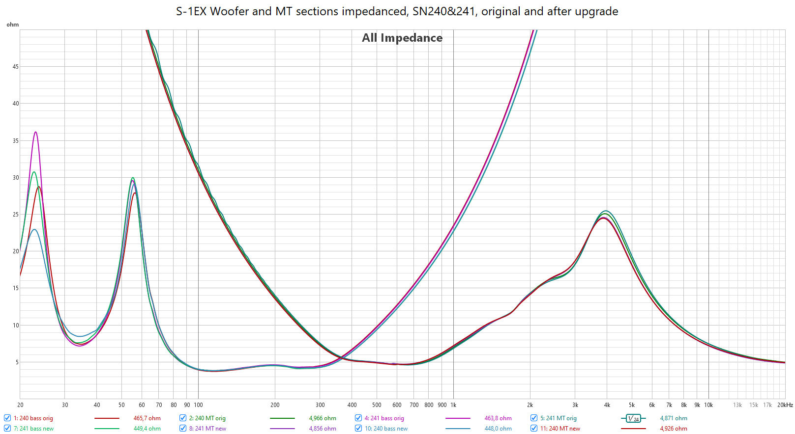
Measurements
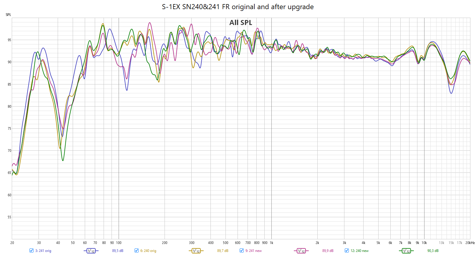
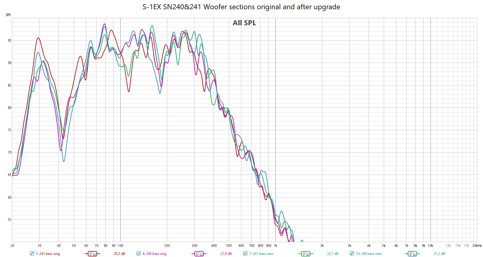
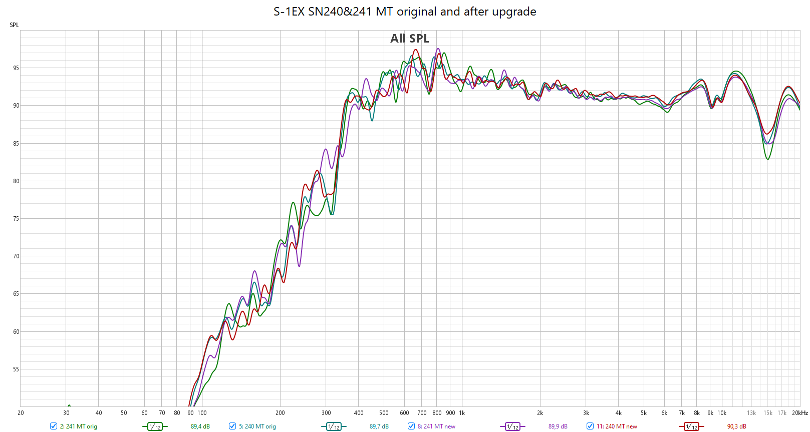
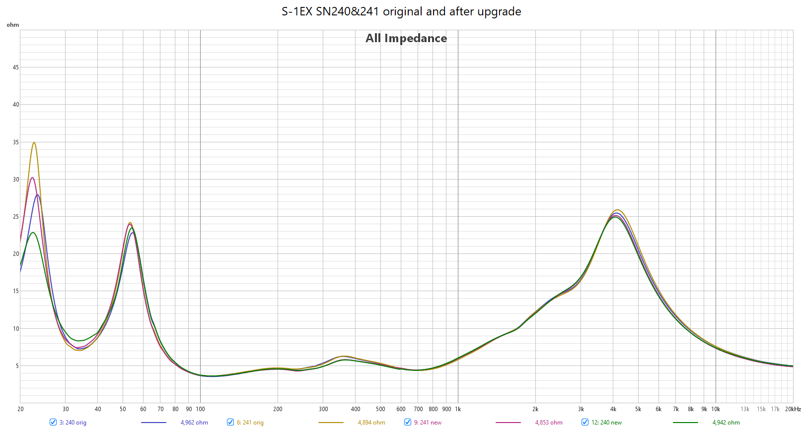
Before any mechanical actions all FRs and impedances were measured for both loudspeakers to to get the baseline to compare to. This also confirmed both loudspeakers were ok.
All measurements were repeated after the upgrade and compared to the baseline measurements, resulting in very good matches. Well, the preparation steps and careful picking of the crossover parts paid off.
All FR measurements were taken with mic distance 60cm from the baffle, measured in room, so I decided not to apply gating and go with smoothing 1/12. Loudspeakers were not measured precisely in the same position in the room hence the differences and the ripples. Anyway, from those measurements it is clear original and new crossovers work identical and there is very good match between them.
Photos of the loudspeakers


