HowTo read graphs and measurements.....
... published on this website
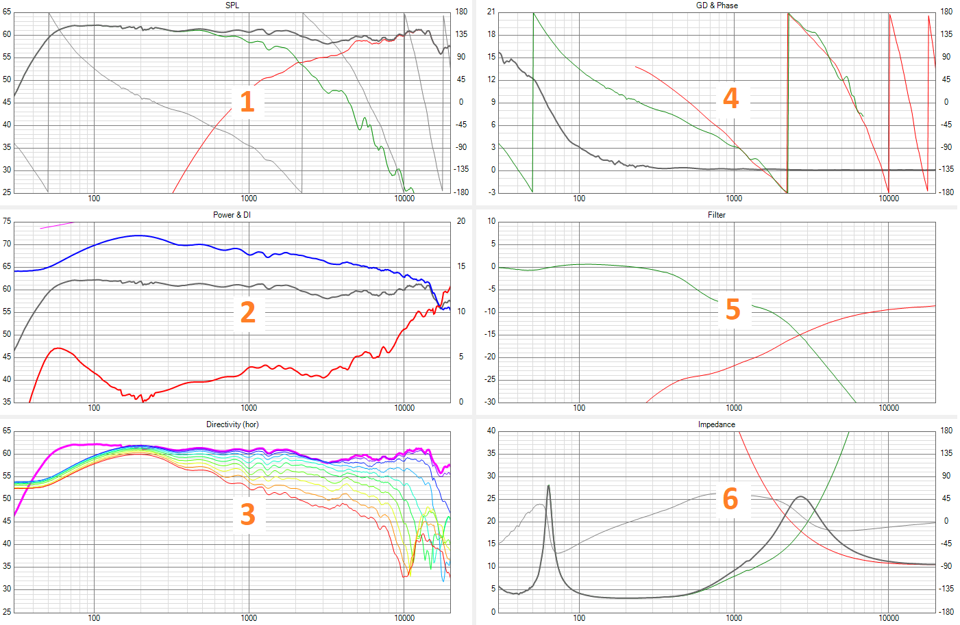
VituixCAD six-pack
As VituixCAD very quickly became my favorite and the only tool for crossover modelling, I usually show this set of graphs. Real measured impedances and frequency responses of individual drivers in the cabinet are input data.

1. Frequency responses for reference axis
In most cases I place reference axis between mid and tweeter. Graph shows responses of all drivers with the crossover and overall frequency response (black trace). Responses are gatted with the impulse window ~4ms, mic distance is 80-100mm. Woofer response usually contains NF measurement of woofer+port, and also bafflestep, merged with FF response around 200-400Hz. No smoothing applied. Shown responses are not SPL calibrated.
2. Power response, ref axis frequency response (FR) and Directivity index
Power response - blue trace
Ref axis frequency response (FR) - gray trace
Directivity index (DI) - red trace, unless stated otherwise, shown for reference angle 0degrees (axial response). DI part below ~300Hz is usually invalid.
3. Horizontal off axis frequency responses
Off axis horizontal frequency responses 0-90degrees, reference axis highlighted (this highlighted trace is used for DI calculation). Only axial FR contains merged NF measurements of the woofer.
Rotation axis for horizontal responses is placed on the surface of the front baffle.
4. Group delay and phase graph
GD - black trace
Color traces - phase responses of individual drivers, used for phase tracking evaluation.
5. Filter graph
Graph shows electrical gains of individual crossover sections.
6. Impedance graph
Graph contains impedances of individual crossover sections, overall impedance and impedance phase. Used for nominal and minimal impedance evaluation.